Power Circuit
Control Circuit

Circuit Operation
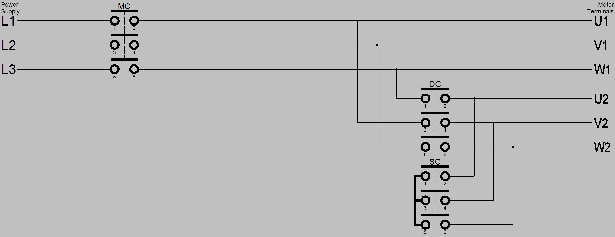
When the start button is pressed its contacts a3-a4 close, the main contactor coil MC is energised which causes it’s main contacts on terminals 1-2, 3-4 and 5-6 to close, it’s normally open auxiliary contact on terminals 13-14 also closes. The auxiliary contact maintains power to the contactor coil when the start button is released. Power is connected from the power supply to the motor terminals U1, V1 and W1. At the same time the star delta timer SDT energises which causes its instantaneous close, delay to open contact on terminals 17-18 to close, this in turn energises the star contactor SC which causes its main contacts on terminals 1-2, 3-4 and 5-6 to close and its auxiliary contact on terminals 21-22 to open. Motor terminals U2, V2 and W2 are connected together thus completing the motor circuit. The motor starts with a reduced voltage on each winding and accelerates to a speed that is load dependant. The voltage reduction is √3 of the line voltage. The star delta timer SDT is a special type of time delay relay that has two contacts. After a preset time the star delta timer SDT instantaneous close delay to open contact on terminals 17-18 opens which de-energises the star contactor coil SC which causes its main contacts on terminals 1-2, 3-4 and 5-6 to open and it’s normally closed auxiliary contact on terminals 11-12 to close. The motor circuit becomes open circuit. The star delta timer SDT delay to close contact on terminals 27-28 closes 50-60milli-seconds after the preset time which opened the contact on terminals 17-18. The additional delay is to allow the star contactor to open and its disconnecting arc to extinguish, it also allows the reset of any mechanical interlock between the star and delta contactors before the delta contactor DC coil is energised. Star delta timer SDT delay to close contact on terminals 27-28 closing energises the delta contactor DC which causes its main contacts 1-2, 3-4 and 5-6 to close and it’s normally closed auxiliary contact on terminals 21-22 to open. The power supply is connected to motor terminals U2, V2 and W2. Thus each winding has the full voltage applied to it, the motor accelerates to full speed.
To stop the motor the stop button is pressed its contacts a1-a2 open which de-energises the energised contactors and timers thus stopping the motor by removing its power supply and resetting the control circuit.
The auxiliary normally closed contacts of the star SC and delta DC contactors are placed into each others coil circuit so that electrically the two contactors cannot be simultaneously energised which would cause a short circuit, this can be seen by examination of the above circuit. However it is normal to mechanically interlock the star and delta contactors in addition to the electrical interlock.
There is a variation of the power circuit where the main contactor is within the delta network this lowers the current in that contactor to √3 of the line current thus savings could be made in the cost of the contactor, however due the short time withstand and type 2 coordination requirements, which are discussed later in this article, the savings are marginal.